.png)
.png)


Expert Method: How to Calculate Cubic Inches of Orbit Hydraulic Motors with 2 Key Formulas
October 11, 2025
Abstract
The accurate determination of an orbit hydraulic motor's displacement, measured in cubic inches, is fundamental to the proper design, selection, and operation of hydraulic systems. This calculation dictates the motor's output torque and speed for a given fluid flow and pressure, directly influencing overall system performance, efficiency, and longevity. This document elucidates the principles behind motor displacement and presents two primary methodologies for its calculation. The first method derives displacement from known operational parameters such as fluid flow rate (GPM) and rotational speed (RPM). The second, conversely, determines the required displacement based on application-specific torque and pressure requirements. An examination of the interplay between displacement, torque, speed, and efficiency is provided, contextualized with practical examples. The discourse extends to encompass crucial conversion between metric and imperial units, the impact of practical variables like fluid viscosity and system pressure, and a systematic guide for motor sizing to prevent common failures associated with improper selection.
Key Takeaways
- Calculate displacement using flow and speed: CID = (GPM × 231) / RPM.
- Determine required displacement from torque: CID = (Torque × 6.2832) / (PSI × Efficiency).
- Correctly size your motor to prevent overheating and premature system failure.
- Master how to calculate cubic inches of orbit hydraulic motors for optimal performance.
- Always account for mechanical and volumetric efficiencies for real-world accuracy.
- Convert between cubic inches (CID) and cubic centimeters (cc) using the 16.387 factor.
Table of Contents
- The Foundational Role of Displacement in Hydraulic Systems
- Understanding the Heart of the Machine: The Orbit Hydraulic Motor
- The First Key Formula: Calculating CID from Known Specifications
- The Second Key Formula: Determining CID for System Design
- A Tale of Two Units: Converting Between Cubic Inches (CID) and Cubic Centimeters (cc)
- Beyond the Formulas: Practical Factors Influencing Motor Selection
- A Step-by-Step Guide to Sizing Your Orbit Motor
- Common Pitfalls in Motor Sizing and How to Avoid Them
- Frequently Asked Questions (FAQ)
- Conclusion
- References
The Foundational Role of Displacement in Hydraulic Systems
Before we can embark on the specific mathematics of calculation, it is profoundly important to first establish a conceptual foundation. What are we truly measuring when we speak of a motor's "displacement"? To grasp this is to grasp the very heart of how a hydraulic system translates fluid power into mechanical work. Without this understanding, the formulas are merely abstract symbols; with it, they become powerful tools for prediction and design.
What is "Displacement" in the Context of a Hydraulic Motor?
Imagine, for a moment, the human lungs. The amount of air you can inhale in a single, deep breath is your lung capacity or volume. In a very similar way, the displacement of a hydraulic motor refers to the volume of hydraulic fluid required to turn the motor's output shaft through one single, complete revolution. It is the motor's "breath" of fluid.
This volume is most commonly expressed in North America and in many industrial contexts as cubic inches per revolution, often abbreviated as CIR or CID (Cubic Inch Displacement). In regions that predominantly use the metric system, you will see this same value expressed as cubic centimeters per revolution (cc/rev).
Think of the internal chambers of the motor. As pressurized fluid from a pump, perhaps an electric hydraulic pump, is forced into these chambers, it pushes against internal surfaces, causing the motor's core components to rotate. The total volume of all the chambers that are filled and emptied to produce that one 360-degree turn is the motor's displacement. A motor with a large displacement is like a person with large lungs; it takes in a large volume of fluid for each rotation. A motor with a small displacement, conversely, requires a much smaller volume of fluid for each turn. This single characteristic is the genetic code of the motor, dictating its core capabilities.
Why Cubic Inches? A Note on Units and Conversions
The use of cubic inches is a legacy of the imperial system of measurement, which remains prevalent in the United States and has a strong historical foothold in many global industries, particularly those related to heavy machinery and automotive applications. A cubic inch is the volume of a cube with each of its three dimensions (length, width, and height) being one inch long.
It is a tangible, if somewhat abstract, unit. To help visualize it, consider a standard six-sided die from a board game. Its volume is typically less than one cubic inch. Now, imagine a small box measuring roughly 2.5 cm on each side; that is approximately one cubic inch. When we say a motor has a displacement of 10 cubic inches, we mean that a volume of fluid equivalent to ten of these little boxes is needed to make its shaft spin around once.
The global nature of manufacturing and engineering, however, means that we must be bilingual in our units. The cubic centimeter (cc), a cornerstone of the metric system, is the other key player. As we will explore in a dedicated section, the ability to convert seamlessly between CID and cc is not just a useful skill but a necessary one for anyone working with components sourced from different parts of the world.
The Direct Relationship Between Displacement, Torque, and Speed
The displacement value of an orbit hydraulic motor is not just a passive specification; it is an active determinant of the motor's two primary performance outputs: torque and speed. The relationship is an elegant, inverse balance.
-
Displacement and Torque: Torque is the rotational force, or twisting power, that the motor can generate. Think of it as the motor's strength. A larger displacement means that the pressurized fluid has a larger internal surface area to push against. Just as using a longer wrench makes it easier to loosen a stubborn bolt, having a larger area for the pressure to act upon generates a higher turning force. Therefore, for a given system pressure (measured in pounds per square inch, or PSI), a motor with a larger displacement will produce a higher output torque. This is why orbit motors, often having large displacements relative to their physical size, are known as Low-Speed, High-Torque (LSHT) devices (Impro Precision, 2023).
-
Displacement and Speed: Speed, measured in revolutions per minute (RPM), is how fast the motor's shaft turns. Here, the relationship is inverse. For a given flow rate of fluid from the pump (measured in gallons per minute, or GPM), a motor with a larger displacement will turn more slowly. This makes intuitive sense. If each rotation requires a large "gulp" of fluid, and the fluid is being supplied at a constant rate, the motor can only complete a few rotations in a given amount of time. Conversely, a motor with a small displacement needs only a small "sip" of fluid per rotation, so for the same flow rate, it will spin much faster.
This fundamental trade-off is the first decision point in any hydraulic motor selection process. Do you need high torque to turn a heavy load, like the auger on a drilling rig? You will likely need a motor with a larger displacement. Do you need high speed to spin a fan blade or a grinding wheel? A motor with a smaller displacement would be the more logical choice. Understanding how to calculate cubic inches of orbit hydraulic motors is the key to navigating this critical balance.
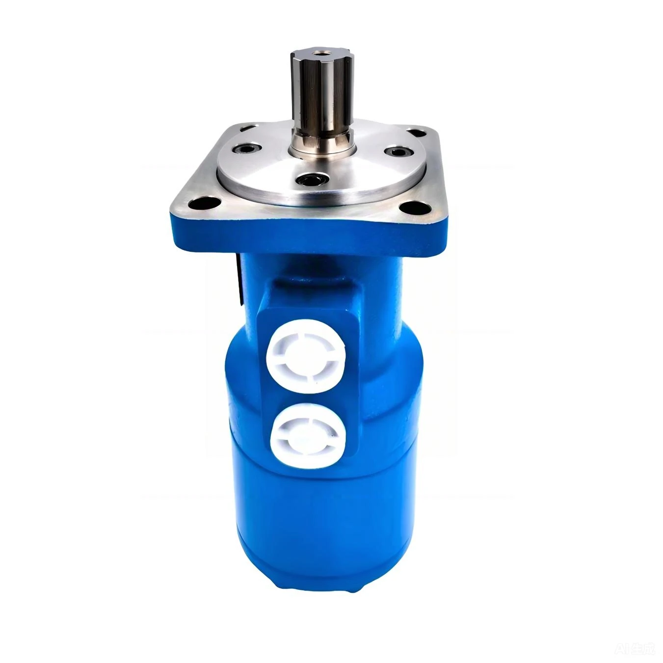
Understanding the Heart of the Machine: The Orbit Hydraulic Motor
To properly calculate the displacement of these remarkable devices, one must appreciate their unique internal architecture. The term "orbit motor" is not arbitrary; it describes the fascinating motion happening within its robust housing. These are not your typical gear or vane motors. Their design is a specialized form of a gerotor motor, engineered specifically to deliver impressive power from a compact form factor.
A Glimpse Inside: The Gerotor/Geroler Mechanism
At the core of every orbit motor is a matched set of gear-like components. Imagine a fixed outer ring with internal teeth. Now, picture a smaller, "star-shaped" inner gear with one fewer tooth than the outer ring. This inner gear is placed inside the outer ring, but it is not centered. It is set off-axis, on an eccentric path. This pairing of an inner and outer gear is known as a "gerotor," a portmanteau of "generated rotor."
As hydraulic fluid is pumped into the assembly, it flows into the expanding chambers created between the teeth of the inner and outer gears. The pressure of the fluid pushes the inner star gear, forcing it to both rotate on its own axis and orbit within the fixed outer ring. It is this unique, planetary-like orbital motion that gives the motor its name. The center of the inner gear traces a circular path as it rolls smoothly around the internal contour of the outer ring.
This motion is then transferred via a splined driveshaft to the motor's output shaft, delivering the smooth, high-torque rotation that these motors are famous for. Some designs, often called "Geroler" motors, add rollers to the tips of the inner star's lobes. These rollers reduce friction and wear, increasing the motor's mechanical efficiency and lifespan, especially under high-pressure conditions. The entire assembly is a marvel of fluid dynamics and mechanical engineering, designed to create the maximum turning force with minimal internal energy loss (ATO.com, 2025).
The Beauty of Low-Speed, High-Torque (LSHT) Performance
The design of the gerotor set is what directly enables the LSHT characteristics of orbit hydraulic motors. Because the inner gear has fewer teeth than the outer ring, the displacement "pockets" formed between them are relatively large. As we discussed earlier, a large volume of fluid per revolution inherently leads to high torque.
Consider trying to open a heavy, solid oak door. If you push near the hinges, you must exert a tremendous amount of force. If you push on the edge farthest from the hinges, the door swings open with much less effort. The internal geometry of an orbit motor effectively gives the hydraulic fluid a very long "lever arm" to push against, multiplying the force generated by the system's pressure.
This allows these motors to directly drive heavy loads without the need for additional gearboxes. A conventional electric motor, for example, might spin at 1800 RPM but produce very little torque. To drive a heavy conveyor belt, it would need a large, complex, and expensive gear reduction system. An orbit motor, on the other hand, can be coupled directly to the conveyor's drive roller and turn it at 50 RPM with immense twisting force. This direct-drive capability simplifies machine design, reduces the number of components, saves space, and increases overall system reliability (FY Hydraulics, 2021). Their compact size and power density make them indispensable in mobile and industrial applications where space and weight are at a premium.
Where You'll Find These Workhorses: Common Applications
Once you know what to look for, you will start to see the applications of orbit hydraulic motors everywhere. Their robustness and LSHT nature make them ideal for the demanding environments of many industries.
- Agriculture: They power the rotating brushes on street sweepers, drive the augers in seeders and spreaders, turn the headers on combines, and operate conveyor systems for harvested crops.
- Construction: You will find them as wheel motors in skid-steer loaders, providing the powerful, independent wheel control needed for maneuverability. They drive concrete mixers, post-hole diggers, and trenching equipment.
- Forestry and Mining: The immense torque is perfect for driving the cutting heads on feller bunchers, operating heavy-duty winches, and powering rock drills.
- Manufacturing and Industrial: They are used in plastic injection molding machines, to drive long conveyor systems, power industrial mixers for chemicals or food products, and operate material handling equipment.
- Marine: On ships and offshore platforms, they are used to operate anchor winches, mooring capstans, and positioning thrusters.
In all these cases, the common requirement is for smooth, controllable, and powerful rotation at relatively low speeds. The orbit motor fulfills this need with an elegance and efficiency that few other prime movers can match (Impro Precision, 2024). Understanding the calculation of their displacement is the first step toward correctly applying them in these and countless other applications.
The First Key Formula: Calculating CID from Known Specifications
We now arrive at the first of our two central mathematical tools. This formula is what you would use when you have an existing hydraulic system and you want to determine the displacement of the motor within it. Perhaps the label on the motor is worn off, or you are troubleshooting a performance issue and need to verify that the installed motor matches the system's design specifications. This method allows you to deduce the motor's displacement by observing its behavior.
The formula is based on the direct relationship between flow, speed, and displacement that we have already discussed.
The Theoretical Displacement Formula: CID = (Flow Rate in GPM × 231) / RPM
Let us state the formula clearly:
Cubic Inch Displacement (CID) = (Flow Rate in Gallons Per Minute × 231) / Rotational Speed in Revolutions Per Minute
This equation is elegant in its simplicity. It tells us that a motor's displacement is directly proportional to the flow rate of fluid it consumes and inversely proportional to the speed at which it turns.
Breaking Down the Components: GPM, 231, and RPM Explained
To use this formula with confidence, we must understand each of its three parts.
-
Flow Rate (GPM): This is the volume of hydraulic fluid that the pump is supplying to the motor, measured in U.S. Gallons Per Minute. This value can often be found in the specifications for the hydraulic pump. For a more accurate, real-world measurement, a hydraulic flow meter can be temporarily installed in the line leading to the motor. It is the "fuel" rate for our hydraulic engine.
-
The Magic Number (231): This constant, 231, is the conversion factor between U.S. gallons and cubic inches. There are exactly 231 cubic inches in one U.S. gallon. This number is the bridge that allows us to reconcile our flow rate (in gallons) with our desired displacement unit (in cubic inches). The term GPM × 231 effectively converts the flow rate from "gallons per minute" into "cubic inches per minute."
-
Rotational Speed (RPM): This is the output speed of the motor shaft, measured in Revolutions Per Minute. How fast is the motor actually turning under load? This can be measured accurately using a device called a tachometer, which can be either a contact type (touching the end of the spinning shaft) or a non-contact, photoelectric type (using a reflective piece of tape on the shaft).
Think about what the formula is doing. The numerator, (GPM × 231), gives us the total volume of fluid in cubic inches flowing through the motor every minute. The denominator, RPM, is the number of revolutions the motor makes in that same minute. When you divide the total volume per minute by the number of revolutions per minute, the "per minute" part cancels out, leaving you with the volume per revolution—which is, by definition, the motor's displacement in cubic inches.
A Practical Walkthrough: Calculating CID for a Skid Steer Auger
Let's make this tangible with an example. Imagine you are a mechanic working on a skid-steer loader with a hydraulic auger attachment used for drilling post holes. The customer complains that the auger is turning too slowly and seems weak. You suspect the wrong motor might have been installed on the attachment. Your goal is to determine the displacement of the currently installed motor.
-
Measure the Flow (GPM): You consult the skid steer's service manual and find that its auxiliary hydraulic circuit is rated to provide a flow of 20 GPM. To be certain, you connect a flow meter and, with the engine at the correct operating speed, you confirm a steady flow of 19.5 GPM going to the auger motor. We will use this more accurate, measured value.
-
Measure the Speed (RPM): You engage the hydraulics and let the auger spin freely (without a load, for this test). Using a digital tachometer, you measure the output shaft of the auger motor spinning at 150 RPM.
-
Apply the Formula: Now you have the two pieces of information you need. You plug them into the formula:
CID = (Flow Rate in GPM × 231) / RPM CID = (19.5 GPM × 231) / 150 RPM CID = 4504.5 / 150 CID = 30.03
The calculated displacement of the motor is approximately 30 cubic inches. You then check the specifications for the auger attachment, and you discover that it is designed to be used with a motor of around 15 cubic inches. The installed 30 CID motor is far too large. This explains everything! With double the displacement, it's no wonder it's turning at half the expected speed and feels "weak" (because the system pressure might not be sufficient to generate the required torque with that large a displacement). You have successfully used the formula to diagnose the problem.
Accounting for Reality: Volumetric Efficiency and Its Impact
The formula as stated gives us the theoretical displacement. It assumes a perfect world where the motor is 100% efficient. In reality, no machine is perfect. There will always be a small amount of internal leakage or "blow-by" within the motor. Some of the high-pressure fluid will slip past the seals of the gerotor set and go directly to the low-pressure outlet port without doing any useful work.
This inefficiency is quantified by the motor's volumetric efficiency. A typical orbit motor might have a volumetric efficiency of 95-98% when new. This means that only 95-98% of the fluid supplied to the motor is actually used to produce rotation; the remaining 2-5% is lost to internal leakage.
To get a more accurate calculation of the motor's actual displacement, you can adjust the formula:
Actual CID = (GPM × 231 × Volumetric Efficiency) / RPM
If you do not know the exact efficiency (it changes with wear, pressure, and fluid viscosity), using the theoretical formula is still an excellent starting point and is often sufficient for most diagnostic and selection purposes. However, being aware of this efficiency factor is the mark of a more sophisticated understanding. When a motor becomes old and worn, its volumetric efficiency drops, leakage increases, and it will spin slower for the same amount of flow, a classic symptom of a worn-out motor.
The Second Key Formula: Determining CID for System Design
Our first formula was for analysis—for figuring out what you have. This second formula is for synthesis—for figuring out what you need. This is the tool of the design engineer, the fabricator, or the enthusiast who is building a new machine or retrofitting an old one. You know the job you need to do, which means you know the torque your application requires. Your task is to select a motor with the correct displacement to achieve that torque using your available system pressure.
The Torque-Based Displacement Formula: CID = (Torque in lb-in × 2 × π) / (Pressure in PSI × Mechanical Efficiency)
Let's present this second crucial formula:
Cubic Inch Displacement (CID) = (Required Torque in lb-in × 6.2832) / (System Pressure in PSI × Mechanical Efficiency)
This equation allows us to work backward from our desired output (torque) to the necessary motor characteristic (displacement).
Deconstructing the Variables: Torque, Pressure, and Pi
Let's examine the elements of this design-oriented formula.
-
Required Torque (lb-in): This is the most critical input and the starting point of your design. It represents the rotational workload. How much twisting force does your application demand? Torque is force multiplied by distance. If you need to lift a 100-pound weight using a winch with a drum radius of 5 inches, your required torque is 100 lbs × 5 inches = 500 lb-in (pound-inches). You must determine this value based on the physics of your specific application. Sometimes this involves calculation, and other times it might be a known specification for a particular task.
-
System Pressure (PSI): This is the pressure your hydraulic power unit (your pump and relief valve assembly) can deliver, measured in Pounds per Square Inch. This is often a known constraint. For example, the hydraulic system on a compact tractor might be designed to operate at a continuous pressure of 2,500 PSI. This is the "effort" you have available to work with.
-
The Constant (2 × π): The number 2 × π (approximately 6.2832) is a constant that arises from the geometry of rotation and the conversion between linear force and rotational torque. It bridges the world of pressure (force per unit area) and torque (force at a radius). For our purposes, we can treat it as a necessary mathematical link that makes the units work out correctly. Its presence is deeply rooted in the physics of how pressure acting over an area within the motor gets converted into torque on the output shaft.
The Nuance of Mechanical Efficiency: A Necessary Consideration
Just as our first formula had to contend with volumetric efficiency, this second formula must account for mechanical efficiency. Mechanical efficiency addresses the internal friction of the motor. Not all of the theoretical torque generated by the pressure is available at the output shaft. Some of it is lost overcoming the friction between the moving parts—the gerotor gears, the splines, the bearings, and the seals.
A typical mechanical efficiency for a good quality orbit motor is around 90-95%. This means only 90-95% of the theoretical force is converted into useful output torque. The rest is lost as heat.
This value is critically important in design calculations. If you ignore it, you will select a motor that is too small for the job. When the motor is put to work, it will fail to produce the required torque, or it will stall. You must always use a realistic mechanical efficiency value, which can usually be found on the performance charts in the motor's datasheet. If you are unsure, using a conservative estimate like 0.90 (for 90% efficiency) is a safe engineering practice.
A Design Scenario: Selecting a Motor for a Conveyor Belt System
Let's put this formula to work. Imagine you are building a conveyor system to move gravel at a quarry. Your engineering analysis shows that to start the belt moving when fully loaded, you need a continuous torque of 4,000 lb-in at the drive roller. Your system is powered by an electric hydraulic pump that operates at a steady 2,000 PSI. You need to choose the right motor.
-
Identify Your Inputs:
- Required Torque = 4,000 lb-in
- System Pressure = 2,000 PSI
- Mechanical Efficiency: You decide to be conservative and assume a mechanical efficiency of 90%, or 0.90.
-
Apply the Formula: You now have all the necessary values to calculate the required displacement.
CID = (Torque in lb-in × 6.2832) / (Pressure in PSI × Mechanical Efficiency) CID = (4,000 × 6.2832) / (2,000 × 0.90) CID = 25132.8 / 1800 CID = 13.96
The calculation tells you that you need a hydraulic motor with a displacement of approximately 14 cubic inches. Now you can consult manufacturer catalogs, like those for a range of high-quality orbit hydraulic motors, and look for a model with a displacement at or slightly above 14 CID. You might select a 15 CID motor to give yourself a small safety margin. By using this formula, you have translated a real-world requirement (moving a loaded conveyor) into a concrete engineering specification (a 15 CID motor).
A Tale of Two Units: Converting Between Cubic Inches (CID) and Cubic Centimeters (cc)
In our increasingly globalized world of engineering and parts sourcing, being fluent in only one system of measurement is a significant handicap. You might perform all your calculations in cubic inches, only to find that the perfect motor from a European or Asian manufacturer is specified in cubic centimeters. The ability to convert quickly and accurately between these two units is essential.
The Simple Conversion Factor: 1 cubic inch ≈ 16.387 cubic centimeters
The relationship between the imperial cubic inch and the metric cubic centimeter is a fixed constant.
- 1 Cubic Inch = 16.387064 Cubic Centimeters
For most practical purposes, rounding this to 16.387 is more than sufficient.
Conversely, to convert from cc to CID:
- 1 Cubic Centimeter = 0.0610237 Cubic Inches
You can calculate this by simply dividing 1 by 16.387.
So, the two key operations are:
- To convert CID to cc, you multiply by 16.387.
- To convert cc to CID, you divide by 16.387.
Let's revisit our conveyor belt example. We calculated a required displacement of 14 CID. Suppose you find a promising motor, but its datasheet lists its displacement as 240 cc. Is it the right size?
Let's convert its cc rating to CID: CID = 240 cc / 16.387 = 14.64 CID
Yes, this 240 cc motor is almost exactly the size you need. It has a displacement of 14.64 cubic inches, which is very close to your calculated requirement of 14 CID.
When to Use Which: Regional and Manufacturer Preferences
As a general rule, you will encounter CID used most frequently by manufacturers based in the United States. It is deeply embedded in the culture of industries like American agriculture and construction.
You will see cc (or cm³/rev, which is the same thing) used almost exclusively by European and many Asian manufacturers. Companies from Germany, Italy, Japan, and Korea will typically specify their hydraulic components in metric units.
For professionals working in regions like South America, Russia, Southeast Asia, the Middle East, and South Africa, it is common to encounter equipment and components from all over the world. A farm in South Africa might have an American-made tractor (using CID) with a European-trenching attachment (using cc). Being able to perform this conversion is not an academic exercise; it is a daily necessity for maintenance and parts replacement.
Table: Quick Conversion Chart for Common Motor Sizes
To aid in quick estimations and build an intuitive feel for the conversion, a reference table can be invaluable. This table shows the approximate equivalents for a range of common orbit motor sizes.
| Displacement (Cubic Inches, CID) | Approximate Displacement (Cubic Centimeters, cc) |
|---|---|
| 3 | 49 |
| 5 | 82 |
| 8 | 131 |
| 10 | 164 |
| 12 | 197 |
| 15 | 246 |
| 18 | 295 |
| 20 | 328 |
| 25 | 410 |
| 30 | 492 |
| 40 | 655 |
| 50 | 819 |
This table serves as a useful mental benchmark. If a motor is specified as 300 cc, a quick glance tells you it will be slightly larger than an 18 CID motor. This kind of intuitive familiarity can save a great deal of time when scanning datasheets and comparing products.
Beyond the Formulas: Practical Factors Influencing Motor Selection
The formulas for how to calculate cubic inches of orbit hydraulic motors provide a powerful and essential starting point. They give you a number, a specific displacement to look for. However, a wise engineer or technician knows that the real world is far more complex than a simple equation. Selecting the right motor involves a more holistic consideration of the entire hydraulic system and the application's demands. Ignoring these practical factors can lead to a choice that is mathematically correct but practically wrong.
The Role of System Pressure: Continuous vs. Intermittent Ratings
Every hydraulic motor datasheet will list at least two pressure ratings: a continuous rating and an intermittent rating.
-
Continuous Pressure Rating: This is the maximum pressure at which the motor can operate for extended periods without sustaining damage or significantly shortening its life. Your normal operating pressure, like the 2,000 PSI in our conveyor example, should always be at or below this continuous rating.
-
Intermittent Pressure Rating: This is a higher pressure that the motor can tolerate for brief periods, typically for a few seconds at a time. This rating accounts for the pressure spikes that can occur in a system, for example, when a load is suddenly started or stopped, or when a directional control valve is shifted quickly.
When you perform your displacement calculation using the torque formula, you should use your system's continuous operating pressure. Then, when you select a motor, you must ensure that its continuous pressure rating is greater than or equal to your system's operating pressure. You must also consider if your system is prone to high-pressure spikes. If it is, you need to select a motor whose intermittent pressure rating can handle those spikes. A motor with a low intermittent rating in a "spiky" system is a recipe for blown seals and premature failure.
Fluid Viscosity and Temperature: The Unseen Influencers
Hydraulic fluid is the lifeblood of the system, and its condition has a profound effect on motor performance. The key property here is viscosity, which is a measure of the fluid's thickness or resistance to flow.
-
High Temperature / Low Viscosity: When hydraulic fluid gets hot, it becomes thinner (its viscosity drops). Thinner oil can more easily leak past the internal seals of the motor. This increases internal leakage, which lowers the motor's volumetric efficiency. The result? The motor will run slightly slower and lose some of its torque-producing capability. Excessive heat is a major enemy of hydraulic systems.
-
Low Temperature / High Viscosity: When the fluid is very cold, such as during a cold-weather startup, it is very thick (high viscosity). This thick oil is difficult to pump and can cause a temporary "starvation" of fluid to the motor. It also increases fluid friction within the motor, which lowers the mechanical efficiency and can cause sluggish performance until the system warms up.
When selecting a motor, you must consider the operating temperature range of your application. If you are operating in a hot climate like the Middle East or Southeast Asia, you need to ensure your system has adequate cooling. You should also choose a high-quality hydraulic fluid with a stable viscosity index (VI), which means its viscosity changes less with temperature fluctuations. The efficiency values you use in your calculations are often based on a specific fluid viscosity and temperature; operating far outside that range will alter the motor's real-world performance.
Matching the Motor to the Pump: Why an electric hydraulic pump must be compatible
A hydraulic motor does not work in isolation. It is part of a system, and its most important partner is the pump. An electric hydraulic pump or an engine-driven pump provides the flow and pressure that the motor converts into work. These two components must be correctly matched.
The pump's flow rate (GPM) determines the motor's potential speed. The pump's pressure relief valve setting determines the maximum system pressure, which dictates the motor's potential torque.
If you connect a motor with a very large displacement to a pump with a very low flow rate, the motor will turn incredibly slowly, which may be unusable for your application. Conversely, if you connect a small-displacement motor to a high-flow pump, the motor may overspeed, exceeding its maximum RPM rating and leading to rapid destruction.
The process is a balancing act. You use the torque formula to determine the displacement you need. Then, you use the flow formula (rearranged to solve for speed: RPM = (GPM × 231) / CID) to verify that the motor you have chosen will produce the desired speed when supplied by your existing or planned pump. If the speed is too high or too low, you may need to reconsider your motor displacement, your pump selection, or even add a flow control valve to the system.
Duty Cycle and Expected Lifespan: Sizing for Longevity
How hard will the motor be working? The duty cycle of an application describes its pattern of work and rest.
- Light Duty: The motor runs for short periods with long rests in between, and often operates well below its maximum pressure and speed ratings. An example might be a hydraulic car lift in a small garage.
- Heavy or Continuous Duty: The motor runs for many hours a day, often at or near its maximum continuous pressure and speed ratings. An example is the drive motor for a primary rock crusher at a mine, which may run 24/7.
Two motors might have the same displacement, but one might be a "standard duty" model while the other is a "heavy duty" model with more robust bearings, stronger shafts, and higher-pressure seals. If you use a standard duty motor in a continuous, heavy-duty application, even if your calculations are correct, it will wear out and fail much faster than a motor designed for that workload. Always be honest about your application's duty cycle and choose a motor built to withstand it. Sizing for displacement is only the first step; sizing for durability is just as important for a reliable, long-lasting system.
A Step-by-Step Guide to Sizing Your Orbit Motor
We have explored the concepts, the formulas, and the practical considerations. Now, let's synthesize this knowledge into a clear, methodical process. Following these steps will guide you from a set of application requirements to a well-chosen hydraulic motor, ensuring you have considered all the critical variables along the way.
Step 1: Define Your Application's Requirements (Torque and Speed)
This is the most fundamental step, and it occurs before any calculations. You must have a clear and quantitative understanding of the work you need the motor to do.
- Determine Required Torque: What is the maximum continuous rotational force the motor must produce? This is your Torque (lb-in). As discussed, this might be calculated from loads and lever arms (like a winch), or it might be a known specification for a piece of equipment. Also, consider the startup torque, which can sometimes be higher than the running torque.
- Determine Required Speed: At what speed does the driven component need to rotate? This is your Speed (RPM). Does it need to be constant or variable? What is the acceptable range of speeds?
You cannot proceed without these two numbers. They are the destination on your engineering map.
Step 2: Determine Your Hydraulic System's Capabilities (Flow and Pressure)
Next, you must understand the power source you have to work with.
- Determine Available Pressure: What is the continuous operating pressure your hydraulic pump and relief valve can provide? This is your Pressure (PSI). This is a hard limit on the force you can generate.
- Determine Available Flow: What is the flow rate your pump can supply at the expected operating pressure? This is your Flow (GPM). This will dictate the speed of your chosen motor.
These two values represent the tools you have at your disposal to achieve the torque and speed requirements from Step 1.
Step 3: Perform the Initial Calculation for Cubic Inches
Now you can turn to the core formulas. You will primarily use the torque-based formula for this design step.
- Calculate Theoretical Displacement: Use the formula: CID = (Torque × 6.2832) / Pressure Remember that Torque is from Step 1 and Pressure is from Step 2. This gives you a first, idealized approximation of the motor displacement you need, without accounting for any real-world losses.
Step 4: Adjust for Efficiencies and Safety Factors
This is where good engineering practice separates a functional design from a fragile one. You must move from the ideal to the real.
- Incorporate Mechanical Efficiency: Take your theoretical CID from Step 3 and divide it by an estimated mechanical efficiency (e.g., 0.90 for 90%). Required CID = Theoretical CID / Mechanical Efficiency This will give you a larger, more realistic displacement value. It ensures the motor can deliver the required torque after accounting for its own internal friction.
- Verify Speed: Now, take this new Required CID and use the flow-based formula (rearranged for speed) to check if your system can provide the necessary speed. Expected RPM = (GPM × 231 × Volumetric Efficiency) / Required CID Use the GPM from Step 2 and a reasonable volumetric efficiency (e.g., 0.95). Does this Expected RPM match the Speed (RPM) you defined in Step 1?
- Iterate if Necessary: If the expected speed is too low, you may need a smaller displacement motor, but that would require higher pressure to achieve the same torque. If the speed is too high, you might need a larger displacement motor, but that might produce more torque than you need and be less efficient. You may need to adjust your choice of motor, pump, or system pressure in an iterative process to find the sweet spot where both torque and speed requirements are met.
- Add a Safety Factor: It is often wise to select a motor that is slightly larger than your calculation indicates, perhaps by 10-15%. This provides a buffer for unexpected loads, fluid temperature changes, and future wear.
Step 5: Consult Manufacturer Datasheets for a Final Selection
Your calculations have given you a target specification (e.g., "I need a heavy-duty motor of approximately 15 CID, rated for 2,500 PSI continuous"). Now you go shopping.
- Review Performance Curves: Do not just look at the headline numbers. Examine the manufacturer's performance charts. These graphs will show you exactly how much torque and speed the motor will produce at various pressures and flow rates. They will also show how the motor's efficiency changes across its operating range.
- Check Physical Dimensions and Mounting: Will the motor physically fit in the space you have available? Does it have the correct shaft type (e.g., keyed, splined) and mounting flange to connect to your equipment?
- Verify Port Types and Seals: Does it have the right hydraulic port types and sizes for your hoses? Are the seals compatible with the type of hydraulic fluid you are using?
- Select a Reputable Supplier: Choose a motor from a known, reputable brand or supplier. The quality of the materials and manufacturing will have a huge impact on the motor's true efficiency and lifespan.
By following this structured, five-step process, you transform the task of how to calculate cubic inches of orbit hydraulic motors from a simple math problem into a comprehensive design methodology, dramatically increasing your chances of success.
Common Pitfalls in Motor Sizing and How to Avoid Them
Even with the correct formulas, it is possible to make errors in judgment that lead to poor system performance or outright failure. Understanding the consequences of these common pitfalls can help you avoid them. Sizing a motor is not just about getting "close enough"; the differences between an undersized, oversized, and correctly sized motor are significant.
The Danger of Undersizing: Premature Failure and Overheating
An undersized motor is one whose displacement is too small to produce the required torque at the available system pressure. This is perhaps the most common and damaging mistake.
- Symptom: The motor stalls, chatters, or is unable to move the load.
- The User's Reaction: A common but incorrect reaction is to increase the system's pressure relief valve setting to try and force the motor to work.
- The Consequence: Running a motor continuously above its rated pressure is a recipe for disaster. The internal stresses on the gerotor set, bearings, and casing can lead to catastrophic failure. At the very least, this over-pressurization dramatically increases internal leakage. This leaked high-pressure fluid generates an immense amount of heat as it squeezes through small clearances. The system overheats, the fluid viscosity drops, and performance gets even worse, creating a vicious cycle that quickly destroys the motor's seals and can damage other system components.
How to Avoid: Trust your calculations. If the torque formula says you need a 15 CID motor, do not try to get by with a 10 CID motor to save money. Always respect the manufacturer's continuous pressure rating.
The Inefficiency of Oversizing: Wasted Energy and Increased Cost
An oversized motor is one whose displacement is significantly larger than what is required for the application. While this might seem like a "safe" option, it comes with its own set of problems.
- Symptom: The motor runs much slower than desired for a given flow rate. The system may feel sluggish or unresponsive.
- The Consequence: A larger motor costs more upfront, takes up more space, and weighs more. More importantly, it is often inefficient. Hydraulic motors have efficiency "sweet spots." Operating a very large motor at a very low percentage of its rated load and pressure is like using a giant dump truck to transport a single shovel of sand. The energy consumed just to turn over the motor's own large rotating mass (its inertia) can be a significant portion of the total energy used. You are wasting fuel or electricity and turning it into unnecessary heat.
How to Avoid: Perform the speed verification step (RPM = (GPM × 231) / CID). If the calculated speed for your oversized motor is far below your target RPM, it is a clear sign that the motor is too large for the available flow rate. Aim for a motor that will operate within the 50-90% range of its rated capabilities for the best balance of performance and efficiency.
Table: Comparison of Motor Sizing Outcomes
| Feature | Undersized Motor | Correctly Sized Motor | Oversized Motor |
|---|---|---|---|
| Performance | Stalls, unable to move load | Smooth, reliable operation | Sluggish, slow speed |
| Operating Pressure | Often runs above rated pressure | Operates at or below rated pressure | Operates far below rated pressure |
| Temperature | Prone to severe overheating | Normal operating temperature | May run warm due to inefficiency |
| Efficiency | Very low (high leakage) | High (operates in sweet spot) | Low (wasted energy) |
| Lifespan | Very short, prone to failure | Long and predictable | Can be long, but not cost-effective |
| Initial Cost | Low | Medium | High |
| Operating Cost | High (due to damage/replacement) | Low | High (due to wasted energy) |
Ignoring Efficiency Ratings: The Gap Between Theory and Reality
A frequent error is to perform calculations without including mechanical and volumetric efficiency. This is basing your design on a perfect world that does not exist.
- The Consequence: If you calculate displacement based on torque but ignore mechanical efficiency, your chosen motor will be too small and will fail to produce the required torque (the undersizing problem). If you calculate speed based on flow but ignore volumetric efficiency, you will overestimate the motor's speed. Your machine will run slower than you planned.
How to Avoid: Always incorporate realistic efficiency values into your formulas. Use 0.85-0.90 for mechanical efficiency and 0.95 for volumetric efficiency if you do not have specific data from the manufacturer. It is always better to be slightly conservative in your estimates.
Mismatching Motor Displacement with System Flow
This pitfall is about failing to see the system as a whole. You might correctly calculate the displacement needed for your torque requirement, but then connect it to a pump that provides a completely inappropriate flow rate.
- The Consequence: If the flow is too high for the chosen displacement, the motor will overspeed, leading to excessive wear and potential failure. If the flow is too low, the motor will turn too slowly to be useful, or it may operate in a "cogging" or jerky manner, especially at very low speeds, because the flow is not smooth enough to pass it from one chamber to the next seamlessly.
How to Avoid: Always complete the loop. After calculating displacement from torque and pressure, immediately use that displacement value with your system's flow rate to calculate the resulting speed. Ensure this speed is within both your application's requirements and the motor's rated speed range. Choosing the right collection of hydraulic motors is about finding a harmonious balance between all system parameters.
Frequently Asked Questions (FAQ)
What is motor displacement in simple terms? Motor displacement is the volume of hydraulic fluid a motor needs to make its shaft turn one full circle. Think of it as the motor's "lung capacity" for fluid. A larger displacement means more torque but slower speed for a given flow.
Why is calculating the cubic inches of an orbit motor so important? Accurate calculation is vital for selecting the right motor. It ensures the motor can produce the required force (torque) to do its job without stalling. It also helps predict the motor's speed, preventing issues like overheating from undersizing or wasted energy from oversizing.
Can I use cubic centimeters (cc) instead of cubic inches (CID)? Yes, absolutely. They are different units for the same measurement. Many manufacturers, especially outside the U.S., use cc. To convert, multiply your CID value by 16.387 to get cc, or divide your cc value by 16.387 to get CID.
What happens if I use a motor with the wrong displacement? If the displacement is too small (undersized), the motor will lack the power to do its job and can overheat and fail if the system pressure is turned up to compensate. If it is too large (oversized), the motor will be slow, inefficient, and unnecessarily expensive.
How do I find the efficiency of a motor for my calculations? The best source is the manufacturer's datasheet, which often provides performance curves showing efficiency at different pressures and speeds. If this is unavailable, using a conservative estimate of 90% (0.90) for mechanical efficiency and 95% (0.95) for volumetric efficiency is a safe starting point for calculations.
Does the type of hydraulic fluid affect the calculation? The formulas themselves do not change. However, the fluid's viscosity, which changes with temperature, affects the motor's real-world efficiency. Hot, thin fluid increases leakage (lowering volumetric efficiency), while cold, thick fluid increases friction (lowering mechanical efficiency). Your calculations are a baseline that will be affected by the fluid's condition.
Where can I find reliable high-torque hydraulic motors? For a wide selection of robust and reliable orbit hydraulic motors suitable for various applications, it is best to consult a specialized supplier. A knowledgeable provider can help you match a motor to your calculated specifications and application demands, ensuring you acquire a quality component.
Conclusion
The process of determining the displacement of an orbit hydraulic motor is far more than a mere academic exercise in mathematics. It is a foundational skill in the practice of fluid power engineering. The two primary formulas—one for analyzing existing systems and one for designing new ones—are the essential instruments for this task. Yet, as we have seen, the numbers derived from these equations are not an end in themselves. They are a starting point, a guide that must be tempered with a practical understanding of real-world factors.
The true mastery of how to calculate cubic inches of orbit hydraulic motors lies in the ability to bridge the gap between theoretical calculation and practical application. It requires an appreciation for the subtle but powerful influences of pressure ratings, fluid characteristics, system matching, and duty cycles. It demands a thoughtful consideration of efficiencies, not as inconvenient subtractions, but as fundamental properties of any physical machine. By embracing this holistic approach—by seeing the motor not as an isolated component but as the heart of a dynamic system—one can make selections that yield not just function, but also efficiency, reliability, and longevity. The calculations are the language we use to speak to the machine; the wisdom is in knowing what to say.
References
ATO.com. (2025). What is an orbital motor working principle? Retrieved from https://ato.com/what-is-an-orbital-motor-working-principle
FY Hydraulics. (2021, January 7). How does orbital hydraulic motor work? Retrieved from https://www.fyhydraulics.com/item/how-does-orbital-hydraulic-motor-work
Impro Precision. (2023, July 31). Understanding the working principle of hydraulic orbital motors. Retrieved from https://www.improprecision.com/understanding-working-principle-hydraulic-orbital-motors/
Impro Precision. (2023, August 1). Advantages of hydraulic orbital motors over other hydraulic motor designs. Retrieved from https://www.improprecision.com/advantages-hydraulic-orbital-motors-hydraulic-motor-designs/
Impro Precision. (2023, September 27). Common problems with hydraulic orbital motors and how to fix them. Retrieved from https://www.improprecision.com/common-problems-hydraulic-orbital-motors-fix/
Impro Precision. (2024, July 4). Orbiting in harmony: Hydraulic orbital motors in hydraulic systems. Retrieved from https://www.improprecision.com/orbiting-harmony-hydraulic-orbital-motors-hydraulic-systems/
Esposito, A. (2017). Fluid power with applications (7th ed.). Pearson.
Henke, R. W. (2007). Introduction to fluid power. Waveland Press.
Majumdar, S. R. (2011). Oil hydraulic systems: Principles and maintenance. McGraw-Hill Education.
Parr, A. (2011). Hydraulics and pneumatics: A technician's and engineer's guide (3rd ed.). Butterworth-Heinemann. https://doi.org/10.1016/C2010-0-65824-0

