.png)
.png)
.png)

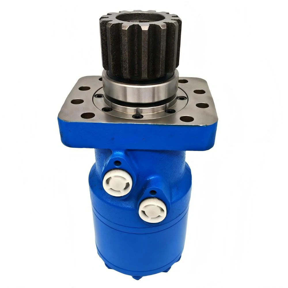
Guida per esperti: Come funziona un motore idraulico orbitale in 4 passi chiave?
13 novembre 2025
Astratto
Il motore orbitale idraulico funziona secondo il principio della conversione della pressione del fluido in forza meccanica di rotazione attraverso un meccanismo di ingranaggi interni. L'elemento centrale del suo funzionamento è il gruppo di ingranaggi, composto da un ingranaggio esterno fisso (statore) e da un ingranaggio interno mobile (rotore) con un numero di denti differenziato. Il fluido idraulico pressurizzato, fornito da una fonte come una pompa idraulica elettrica, viene convogliato nel motore attraverso un commutatore o una valvola. Il fluido riempie le camere di volume in espansione create dall'ingranaggio eccentrico del rotore e dello statore. Il differenziale di pressione risultante sul rotore lo costringe a orbitare all'interno dello statore. Questo movimento orbitale viene poi tradotto in una rotazione concentrica, ad alta coppia e a bassa velocità dell'albero di uscita tramite un albero di trasmissione specializzato. Il fluido depressurizzato viene contemporaneamente espulso dalle camere di contrazione e restituito al serbatoio del sistema. Questo ciclo continuo consente al motore di produrre una coppia significativa da un design compatto ed efficiente, che lo rende una pietra miliare in varie applicazioni industriali e mobili.
Punti di forza
- Il fluido pressurizzato crea un differenziale di forza all'interno del gruppo Gerotor, dando inizio al movimento.
- Il rotore orbita all'interno dello statore, guidato dal riempimento sequenziale delle camere sigillate.
- Un albero di trasmissione converte l'orbita eccentrica del rotore'in una rotazione regolare dell'albero di uscita.
- La comprensione del funzionamento di un motore orbitale idraulico rivela la sua natura di motore a coppia elevata e bassa velocità.
- Una corretta manutenzione dei fluidi è fondamentale per la longevità e l'efficienza del motore.
- Il cuore del progetto'è il gruppo Gerotor, con il suo esclusivo profilo di ingranaggi cicloidali.
Indice dei contenuti
- Uno sguardo fondamentale alla potenza idraulica
- Fase 1: Ingresso della potenza - Pressurizzazione del fluido e flusso diretto
- Fase 2: Il cuore della macchina - Il set di motori e la generazione del movimento
- Fase 3: Dall'orbita all'uscita - Tradurre il movimento in coppia utilizzabile
- Fase 4: Completamento del circuito - Scarico del fluido e ciclo continuo
- Caratteristiche distintive: Tipi principali di motori orbitali
- Metriche di prestazione e selezione intelligente
- Impatto globale: Applicazioni dei motori idraulici Orbit
- Sostenere l'energia: Manutenzione e risoluzione dei problemi
- Domande frequenti
- Una riflessione conclusiva sull'eleganza meccanica
- Riferimenti
Uno sguardo fondamentale alla potenza idraulica
Prima di poter apprezzare appieno l'intricata danza di ingranaggi e fluidi all'interno di un motore orbitale, è necessario prima comprendere i principi fondamentali che gli danno vita. L'intero campo dell'idraulica si basa su una semplice ma profonda osservazione sulla natura dei fluidi. Immaginate di avere un contenitore pieno d'acqua. Se si applica una pressione a un singolo punto della superficie dell'acqua, questa non rimane confinata in quel punto. Al contrario, viene trasmessa in modo uguale e inalterato a ogni altro punto dell'acqua e alle pareti del contenitore stesso. Questa è l'essenza della Legge di Pascal'un principio formulato dal matematico e fisico francese Blaise Pascal nel XVII secolo. È questa trasmissione di forza attraverso un fluido incomprimibile che costituisce la base di ogni sistema idraulico, dai freni della vostra auto ai massicci bracci di un escavatore da cantiere.
Un sistema idraulico, nella sua forma più semplice, agisce come un moltiplicatore di forze. Prende una forza in ingresso e, incanalando il fluido, la trasforma in una forza in uscita molto più grande. I componenti principali di un sistema di questo tipo sono un serbatoio per contenere il fluido idraulico (in genere un olio speciale), una pompa per creare il flusso del fluido, valvole per dirigere il flusso e un attuatore per convertire l'energia del fluido in lavoro meccanico. Questo attuatore può essere lineare, come un cilindro idraulico che spinge e tira, o rotativo, ed è qui che entra in gioco il nostro soggetto, il motore idraulico (Eng.libretexts.org, 2025). La pompa non crea pressione, ma crea un flusso. La pressione si genera quando il flusso incontra una resistenza, come i componenti interni di un motore.
La fonte del flusso: la pompa idraulica elettrica
La forza motrice di quasi tutti i moderni sistemi idraulici industriali è la pompa. Mentre alcuni possono essere azionati da motori a combustione interna, un gran numero di essi è alimentato da motori elettrici, creando quella che chiamiamo pompa idraulica elettrica. Questo dispositivo è il cuore del sistema, che preleva il fluido dal serbatoio e lo spinge nel circuito. È un convertitore di energia, che trasforma l'energia elettrica che alimenta il motore nell'energia cinetica del fluido in movimento. Esistono vari tipi di pompe: pompe a ingranaggi, pompe a palette e pompe a pistoni, ognuna con le proprie caratteristiche in termini di capacità di pressione e consistenza del flusso. La scelta della pompa è una decisione critica per la progettazione, in quanto determina la potenza e la velocità potenziali disponibili per gli attuatori a valle. La pompa idraulica elettrica fornisce un flusso costante e affidabile di fluido che è la linfa vitale del motore, in attesa di essere convertito in coppia.
Pompe e motori: Una storia di due funzioni
È un punto comune di confusione iniziale vedere una pompa idraulica e un motore idraulico e pensare che siano intercambiabili. Strutturalmente possono sembrare molto simili. Una pompa a ingranaggi e un motore a ingranaggi, ad esempio, contengono entrambi una serie di ingranaggi ingranati all'interno di un alloggiamento. La differenza fondamentale sta nella loro funzione e nella direzione di conversione dell'energia. Una pompa, come abbiamo visto, riceve in ingresso una rotazione meccanica (da un motore elettrico o da un motore) e la converte in uscita in un flusso di fluido. In questo modo aziona il fluido. Un motore idraulico, al contrario, riceve in ingresso il flusso del fluido e lo converte in uscita in rotazione meccanica (coppia e velocità). Il fluido aziona il motore.
Pensate a un ventilatore elettrico e a una turbina eolica. Un ventilatore utilizza l'energia elettrica per far girare le pale e creare un flusso d'aria. Una turbina eolica utilizza il flusso d'aria per far girare le pale e creare energia elettrica. Sono due facce della stessa medaglia, una che aziona il mezzo e l'altra che viene azionata da esso. Lo stesso vale per le pompe e i motori idraulici. La pompa genera il "vento" del fluido idraulico e il motore agisce come "turbina", sfruttando quel flusso per svolgere un lavoro utile (Hidraoil.com, 2023). Il nostro obiettivo, il motore orbitale, è un tipo di attuatore rotante particolarmente elegante ed efficace, una "turbina" specializzata progettata per specifici tipi di lavoro.
Fase 1: Ingresso della potenza - Pressurizzazione del fluido e flusso diretto
Il viaggio della potenza all'interno di un motore idraulico orbitale non inizia all'interno del motore stesso, ma molto più a monte, nella pompa. La pompa idraulica elettrica pressurizza il fluido idraulico, caricandolo di energia potenziale. Questo fluido pressurizzato viaggia attraverso tubi e tubazioni fino a raggiungere la porta di ingresso del motore. Questa è la porta d'ingresso. La prima azione per capire come funziona un motore idraulico orbitale è tracciare il percorso di questo fluido ad alta pressione che entra nell'alloggiamento del motore, pronto a iniziare il suo lavoro.
La pressione del fluido è una misura della forza che può esercitare per unità di superficie. La portata, misurata in litri al minuto o galloni al minuto, determina la velocità potenziale del motore. La combinazione di pressione e portata definisce la potenza idraulica totale disponibile. Quando raggiunge il motore, questo flusso di fluido eccitato non inonda semplicemente l'intera cavità interna. Deve essere controllato con precisione e indirizzato in punti specifici in momenti specifici. Questo compito critico di distribuzione è affidato a un componente noto come commutatore o, in alcuni progetti, a una valvola distributrice.
La valvola di distribuzione: Il controllore del traffico
Immaginate una porta girevole con più scomparti. La valvola distributrice funziona in modo simile, agendo come un sofisticato controllore del traffico per il fluido idraulico. Si tratta di una piastra o di un cilindro lavorato con precisione e dotato di una serie di passaggi che si allineano con le porte della sezione di potenza del motore'il gruppo Gerotor. Mentre il motore ruota, la valvola del distributore ruota in sincronia (o è temporizzata), aprendo continuamente un percorso per l'ingresso del fluido ad alta pressione nelle camere corrette e aprendo contemporaneamente un percorso per l'uscita del fluido di scarico a bassa pressione dalle altre camere.
Questo componente è il cervello dell'interfaccia fluido-meccanica. Senza di essa, la pressione del fluido verrebbe applicata in egual misura a tutte le parti interne, dando luogo a un blocco idraulico privo di forza netta per produrre la rotazione. La valvola distributrice assicura che la pressione sia sempre applicata dove può fare il massimo lavoro - nelle camere che si espandono in volume - e che il fluido possa uscire dalle camere che si contraggono. La tempistica e la precisione dell'azione della valvola sono fondamentali per il funzionamento regolare e l'efficienza del motore. I diversi progetti di motori utilizzano diversi tipi di valvole, come le valvole a cursore o le valvole a disco, ciascuna con i propri vantaggi in termini di capacità di flusso, gestione della pressione e perdite interne.
| Caratteristica | Valvola a cursore Motore orbitale | Valvola a disco Motore orbitale |
|---|---|---|
| Design della valvola | Un "cursore" cilindrico con terreni e scanalature scorre o ruota per dirigere il flusso. | Un disco piatto e rotante con porte a forma di rene si allinea ai passaggi. |
| Percorso del flusso | In genere sono più lunghi e complessi, il che può comportare perdite di carico più elevate. | Percorso di flusso più breve e diretto, che generalmente porta a minori perdite di carico. |
| Efficienza | Può avere un'efficienza volumetrica leggermente inferiore a causa dei percorsi di tenuta più lunghi del cursore. | Spesso offre una maggiore efficienza volumetrica e complessiva grazie alla migliore tenuta e al flusso. |
| Tempistica | La temporizzazione è controllata dal collegamento tra il cursore e l'albero principale. | La valvola a disco è azionata direttamente dall'albero motore, garantendo una perfetta sincronizzazione con il Gerotor. |
| Uso comune | Applicazioni generiche, spesso presenti in progetti più vecchi o meno impegnativi. | Applicazioni ad alte prestazioni in cui l'efficienza e la fluidità di funzionamento a bassa velocità sono fondamentali. |
La natura del fluido di lavoro
Si parla di "fluido idraulico", ma vale la pena soffermarsi un attimo su cosa sia questa sostanza e perché le sue proprietà siano così importanti. È molto più di un semplice olio. Un fluido idraulico di alta qualità è una formulazione complessa progettata per svolgere più funzioni contemporaneamente. Il suo ruolo principale è quello di trasmettere la potenza, il che richiede che sia quasi incomprimibile. Deve anche lubrificare la miriade di parti mobili della pompa e del motore, riducendo l'usura e l'attrito. Pensate alle strette tolleranze tra il rotore e lo statore di un motore orbitale: senza un film lubrificante, si formerebbero rapidamente gocce e grippaggi.
Inoltre, il fluido deve allontanare il calore dai componenti in funzione e trasportarlo a un serbatoio o a un dispositivo di raffreddamento dove può essere dissipato. Contiene anche additivi per prevenire la ruggine, la corrosione e la formazione di schiuma, che potrebbe introdurre compressibilità nel sistema e renderlo "spugnoso". La viscosità del fluido - la sua resistenza al flusso - è un equilibrio delicato. Se è troppo denso, crea un attrito eccessivo ed è difficile da pompare. Se è troppo sottile, potrebbe non fornire un film lubrificante adeguato alle alte temperature. Il mantenimento della pulizia e dell'integrità del fluido è l'aspetto più importante della manutenzione dell'impianto idraulico. I contaminanti agiscono come un abrasivo, consumando rapidamente le superfici interne lavorate con precisione e distruggendo il motore dall'interno.
Fase 2: Il cuore della macchina - Il set di motori e la generazione del movimento
Abbiamo seguito il fluido pressurizzato attraverso la porta di ingresso e la valvola del distributore. Ora arriva al cuore del motore, il gruppo di componenti che esegue la magica conversione della pressione del fluido in movimento meccanico. Questo è il gruppo Gerotor. Il nome stesso è un portmanteau di "Generated Rotor", che allude alla sua geometria unica (Ato.com, 2025). Questo meccanismo è la caratteristica distintiva di tutti i motori idraulici orbitali ed è la chiave per comprendere la loro notevole capacità di produrre una coppia elevata a basse velocità.
The Gerotor set consists of two primary parts: a stationary outer ring gear, called the stator, and an internally meshing moving gear, called the rotor. The stator has a set of internal lobes, which are smooth, curved teeth. The rotor, which fits inside the stator, has a set of external teeth, also with a specific curved profile. The critical design element is that the rotor always has one fewer tooth than the stator. For example, a common configuration is a stator with seven lobes (N) and a rotor with six teeth (N-1).
The Geometry of Motion: An Eccentric Dance
Because the rotor has fewer teeth than the stator, its center is not a fixed point. As the rotor turns, its center follows a small circular path relative to the center of the stator. It orbits. This is the origin of the motor's name. Think of the Earth orbiting the Sun. The Earth is spinning on its own axis while also revolving around a central point. The rotor in an orbital motor does something similar; it both rotates on its own center and orbits around the stator's center.
This eccentric arrangement means that as the rotor turns within the stator, the teeth of the two parts are constantly meshing and unmeshing in a specific sequence. As they do, they form a series of sealed, continuously changing volume chambers between the rotor teeth and the stator lobes. At any given moment, some of these chambers are expanding in volume, while others are contracting. It is this dynamic creation of expanding and contracting chambers that the distributor valve exploits.
How Pressure Creates Force
Let us visualize the process. The distributor valve directs the high-pressure inlet fluid into the chambers that are currently growing in size. The fluid pushes against the surfaces of both the stator and the rotor in that chamber. Because the stator is fixed to the motor housing, it cannot move. The rotor, however, is free to move. The pressure acting on the face of the rotor tooth creates a force.
Now, consider the chambers on the opposite side of the Gerotor set. At the same time, the distributor valve is connecting these chambers—which are contracting in volume—to the low-pressure outlet port. This allows the fluid that has already done its work to be pushed out of the motor. The result is a significant pressure differential across the rotor. On one side, you have high-pressure fluid pushing on the rotor teeth. On the other side, you have low-pressure fluid offering little resistance. This imbalance of forces is what compels the rotor to move. It is not just pushed; it is pushed into the path of least resistance, which is the continuous rolling or orbiting motion within the stator. The force is applied over the entire surface area of the tooth, and it is this large area that begins to explain the motor's high torque output. The rotor is effectively "rolled" around the inside of the stator by the hydraulic pressure, like a coin rolling around the inside of a funnel.
Gerotor vs. Geroler™: An Evolutionary Step
A key innovation in orbital motor design was the introduction of rollers. In a standard Gerotor set, the tips of the rotor teeth make direct, sliding contact with the lobes of the stator. While effective, this creates friction, which generates heat and represents an energy loss. The Geroler™ design, a name trademarked by the Eaton Corporation but now used more generally, improves upon this by placing cylindrical rollers into the pockets of the stator.
In this configuration, the rotor teeth do not slide against the stator. Instead, they press against these rollers, which are free to turn. The contact becomes rolling friction instead of sliding friction. As anyone who has ever tried to push a heavy box versus pulling it on a wheeled cart knows, rolling friction is significantly lower than sliding friction. This seemingly small change has a profound impact. It reduces wear, lowers heat generation, and increases the mechanical efficiency of the motor, especially at startup (low speed) and under high pressure. This allows the motor to produce smoother torque and last longer, making it the preferred choice for most modern, demanding applications.
Fase 3: Dall'orbita all'uscita - Tradurre il movimento in coppia utilizzabile
We have established how hydraulic pressure forces the rotor to perform its characteristic orbital dance within the stator. This motion, however, is complex. The center of the rotor is moving in a circle, and the rotor itself is rotating slowly relative to its own center. This is not yet the simple, usable rotation we need to turn a wheel or a winch drum. The next step in understanding how a hydraulic orbital motor works is to see how this complex orbital motion is converted into the pure, concentric rotation of the output shaft. This is the job of the driveshaft, often called a splined shaft or, colloquially, a "dog bone."
The driveshaft is a short, robust shaft with splines (a series of ridges or teeth) on both ends. One end engages with matching internal splines in the center of the rotor. The other end engages with internal splines in the output shaft of the motor. The output shaft is the part of the motor that extends outside the housing and connects to the load. Unlike the rotor, the output shaft is mounted in bearings that constrain it to rotate perfectly around a fixed, central axis.
The Ingenious Coupling
The driveshaft acts as a clever mechanical linkage that decouples the eccentricity of the rotor from the output shaft. As the rotor orbits, the driveshaft's splines allow it to accommodate the rotor's shifting center. The shaft effectively "wobbles" along with the rotor's orbit. However, because its other end is firmly engaged with the concentrically fixed output shaft, it can only transmit the rotational component of the rotor's motion. It filters out the orbital component.
Imagine holding a pencil loosely in your fist. If you move your fist in a small circle (the orbit), while also slowly twisting the pencil (the rotation), a gear attached to the end of the pencil would turn. The driveshaft performs a similar function, but with much greater precision and strength. It takes the combined orbit-plus-rotation of the rotor and transmits only the rotation to the output shaft, resulting in a smooth, continuous turning motion.
The Genesis of High Torque
The defining characteristic of an orbital motor is its ability to produce very high torque at relatively low speeds. This is why they are often categorized as Low-Speed, High-Torque (LSHT) motors. The "high torque" aspect is a direct consequence of the motor's internal geometry and the principles of hydraulics.
Torque is rotational force. It is calculated as force multiplied by the distance from the center of rotation at which that force is applied (the lever arm). In the orbital motor, the hydraulic pressure acts over the large surface area of the rotor teeth. This generates a very large force. This force is then applied at a certain distance from the center of the stator, creating the initial rotational impetus.
More importantly, the internal gearing itself provides a significant gear reduction. For every single rotation of the output shaft, the rotor must complete multiple orbits inside the stator. The exact ratio depends on the number of teeth. For our example of a 6-tooth rotor and a 7-lobe stator, the output shaft rotates 1/6th of a revolution for every full orbit of the rotor. This means the output speed is significantly reduced compared to the speed of the orbiting rotor, and just as with a set of mechanical gears, when you reduce speed, you multiply torque. The orbital motor has this large gear reduction built directly into its power-generating mechanism. It is like having a powerful engine and a heavy-duty gearbox all in one compact package. This is what allows a motor that can fit in your hand to turn the heavy auger on a piece of farm equipment.
| Parametro | High-Speed, Low-Torque (HSLT) Motor (e.g., Gear Motor) | Low-Speed, High-Torque (LSHT) Motor (e.g., Orbital Motor) |
|---|---|---|
| Intervallo di velocità tipico | 500 – 5000+ RPM | 0 – 1000 RPM (often much lower) |
| Torque Output | Low to moderate. | Very high, especially relative to its size. |
| Internal Gearing | Minimal or no internal gear reduction. | Significant inherent gear reduction from the Gerotor principle. |
| Size & Weight | Can be compact, but requires external gearing for high-torque tasks. | Very compact and power-dense for the torque produced. |
| Applicazioni comuni | Fan drives, auxiliary functions, power steering pumps. | Conveyor belts, agricultural machinery, winches, wheel drives. |
| Principio di funzionamento | Direct fluid push on gears or vanes with high rotational speed. | Fluid pressure creates a large force with high leverage and gear reduction. |
Fase 4: Completamento del circuito - Scarico del fluido e ciclo continuo
The process of generating torque is not a one-time event; it is a continuous, cyclical flow of energy. For the motor to keep turning, the fluid that has expended its energy must be efficiently removed to make way for the next charge of high-pressure fluid. This final step closes the loop and is just as critical as the power-generating phase. The entire operation relies on a constant, uninterrupted cycle of fluid entering, working, and exiting.
As we saw, the distributor valve directs high-pressure fluid to the expanding chambers of the Gerotor set. Simultaneously, the rotor's motion is causing the chambers on the opposite side to decrease in volume. The fluid trapped in these contracting chambers must go somewhere. The same distributor valve that controls the inlet flow also provides the escape route. Its precisely timed rotation opens a path from these contracting chambers to the motor's outlet port.
The Gentle Push Outward
The fluid in the contracting chambers is now at a much lower pressure, having transferred most of its energy to the rotor. It does not exit under its own power; rather, it is gently but firmly displaced by the mechanical action of the chamber shrinking. The rotor, driven by the high pressure on the other side, effectively squeezes the spent fluid out into the outlet passage. This ensures that the chambers are empty and ready to receive a new charge of high-pressure fluid when they cycle back around to the inlet side.
This coordinated action of filling and emptying is what allows for smooth, continuous rotation. If the exhaust fluid were not removed efficiently, pressure would build up in the contracting chambers, creating a back-pressure that would oppose the motor's rotation. This would dramatically reduce the net torque output and lower the overall efficiency of the motor. The design of the outlet passages and the distributor valve is therefore optimized to present as little resistance as possible to the outgoing flow.
Return to the Reservoir
Once the low-pressure fluid passes through the outlet port, it travels through return lines back to the hydraulic reservoir. The reservoir is more than just a holding tank. It gives the fluid a chance to cool down, as the heat absorbed from the motor and pump is dissipated through the tank's walls or a dedicated heat exchanger (cooler). It also allows any air bubbles that may have entered the system to rise to the surface and escape. Finally, it provides a place for contaminants and debris to settle at the bottom, away from the pump's suction line, where they can be captured by filters.
From the reservoir, the cooled, clean fluid is drawn back into the suction side of the electric hydraulic pump, where it is re-pressurized, and the entire cycle begins anew. A single drop of hydraulic fluid might make this circuit—from pump to motor and back again—thousands of times in its service life, each time carrying a parcel of energy to be converted into useful mechanical work. The integrity of this closed loop is fundamental to the reliability and longevity of the entire hydraulic system. Any leaks, both external (dripping oil) and internal (fluid bypassing seals inside the motor), represent a loss of energy and a reduction in performance.
Caratteristiche distintive: Tipi principali di motori orbitali
While all orbital motors operate on the same fundamental Gerotor principle, they are not a monolithic category. Engineers have developed several variations to optimize performance for different applications, pressures, and flow rates. The most significant distinctions lie in the design of the distributor valve and the interface between the rotor and stator. Understanding these differences is key to selecting the right motor for a specific task. The two primary valve designs are the spool valve and the disc valve.
Spool Valve Design
In a spool valve orbital motor, the distribution of fluid is controlled by a cylindrical spool that rotates in sync with the main shaft. The spool has a series of grooves and lands (the raised sections between grooves) machined into it. As it turns, these grooves and lands align with ports in the motor housing, directing high-pressure fluid to the appropriate Gerotor chambers and venting low-pressure fluid. This design is robust and was common in earlier generations of orbital motors. However, the fluid must often travel a relatively long and winding path to get from the spool to the Gerotor set. This can create a pressure drop, which is a form of energy loss, slightly reducing the motor's overall efficiency.
Disc Valve Design
A more modern and generally more efficient design is the disc valve motor. In this configuration, the spool is replaced by a flat, rotating disc that sits directly against the Gerotor set. The disc has kidney-shaped ports machined into it. This valve disc is driven by the same driveshaft that turns the output shaft, ensuring perfect timing. As it rotates, its ports slide over corresponding openings in the stationary end plate of the Gerotor, distributing the fluid.
The primary advantage of the disc valve is that it provides a much shorter, more direct path for the fluid. This minimizes the pressure drop and improves volumetric efficiency, which is a measure of how effectively the motor converts fluid flow into rotation without internal leakage. The improved fluid dynamics and better sealing of the disc valve design typically result in higher overall efficiency, smoother operation at very low speeds, and a longer service life, particularly in high-pressure applications. For these reasons, disc valve motors have become the standard for many demanding industrial and mobile hydraulic systems.
Metriche di prestazione e selezione intelligente
Choosing the correct hydraulic motor for an application is a critical engineering decision that goes beyond simply knowing how it works. It requires a careful evaluation of several key performance parameters to ensure the motor can meet the demands of the job reliably and efficiently. Matching the motor's capabilities to the load's requirements is essential for system performance, longevity, and safety. A prospective buyer must consider displacement, torque rating, speed, pressure, and efficiency.
Spostamento
Displacement is perhaps the most fundamental specification of any hydraulic motor. It is the theoretical volume of fluid that the motor will accept to turn its output shaft through one full revolution. It is typically measured in cubic centimeters per revolution (cc/rev) or cubic inches per revolution (in³/rev). A motor with a larger displacement will require more fluid to turn once, but it will also produce more torque for a given pressure. A smaller displacement motor will spin faster for a given flow rate but will produce less torque. Displacement is the primary factor in determining the relationship between flow rate and speed, and between pressure and torque.
Torque and Speed
Torque is the rotational force the motor can produce and is the main reason for selecting an LSHT motor like an orbital. It is rated in Newton-meters (Nm) or pound-feet (lb-ft). The theoretical torque of a motor is directly proportional to its displacement and the system's working pressure. The actual torque available at the shaft will be slightly less due to mechanical friction. Speed, measured in revolutions per minute (RPM), is directly proportional to the flow rate of fluid supplied to the motor and inversely proportional to the motor's displacement. A key consideration is the motor's minimum and maximum continuous speed rating, as well as its ability to operate smoothly and without "cogging" at the very low end of its speed range.
Pressure and Efficiency
Pressure ratings indicate the maximum fluid pressure the motor is designed to handle. There is typically a continuous pressure rating for normal operation, an intermittent rating for short-term peaks, and a peak rating that should never be exceeded. Operating above the continuous rating can drastically reduce the motor's lifespan.
Efficiency is a measure of how well the motor converts hydraulic power into mechanical power. It is broken down into two main components. Volumetric efficiency describes how well the motor prevents internal leakage; a motor with 95% volumetric efficiency means that 5% of the fluid supplied to it leaks past the internal seals without producing work. Mechanical efficiency describes the energy lost to internal friction. The product of these two is the overall efficiency, which is a critical factor in system design, as it impacts heat generation and energy consumption. High-quality motori idraulici often boast overall efficiencies well above 90%.
Impatto globale: Applicazioni dei motori idraulici Orbit
The unique combination of compact size, high torque, and low speed has made the orbital motor an indispensable component in a vast array of machinery across the globe. Their robust and simple design makes them particularly well-suited for the demanding environments often found in target markets like South America, Russia, Southeast Asia, the Middle East, and South Africa.
In agriculture, these motors are the workhorses behind the rotation of augers on seeders and combines, the turning of conveyor belts on harvesters, and the drive systems for sprayers. Their ability to deliver precise, high-torque motion is perfect for these tasks. In Russia's vast farmlands or Brazil's extensive soy plantations, the reliability of these motors is paramount during short planting and harvesting seasons.
The construction industry relies heavily on orbital motors. They power the wheel drives on skid-steer loaders, giving them their characteristic agility and pushing power. They turn the drums on small concrete mixers, drive sweepers and attachments, and provide the slewing (rotating) function for small cranes and aerial work platforms. In the rapidly developing urban centers of Southeast Asia and the Middle East, the compact power of these motors is essential for machinery operating in tight spaces.
In the marine sector, they are used to power winches, capstans, and steering systems on fishing vessels and workboats. Their sealed design and robust construction stand up well to the harsh, corrosive saltwater environment, a common challenge from the coasts of South Africa to the archipelagos of Indonesia.
Manufacturing and material handling industries use orbital motors to drive conveyor systems, power industrial mixers, and position heavy components with precision. Their smooth, controllable low-speed operation is ideal for applications where steady, powerful movement is required. The ability to start and stop smoothly under full load makes them superior to many electric motor and gearbox combinations for these types of tasks.
Sostenere l'energia: Manutenzione e risoluzione dei problemi
A hydraulic orbital motor is a marvel of robust engineering, but it is not invincible. Its longevity and performance are directly tied to the health of the hydraulic system as a whole, and proper maintenance is not merely recommended; it is obligatory for reliable operation. The overwhelming majority of premature motor failures can be traced back to a single culprit: contaminated hydraulic fluid.
The Primacy of Fluid Health
As discussed, hydraulic fluid is the lifeblood of the system. If that blood becomes contaminated with dirt, water, or metal particles, it turns from a lubricant into a liquid grinding compound. These contaminants are carried at high velocity through the motor, where they erode the precision-machined surfaces of the Gerotor set, the distributor valve, and the driveshaft. This wear opens up the tight internal clearances, leading to increased internal leakage. The motor loses volumetric efficiency, meaning it gets weaker and slower. The contamination can also clog small orifices, leading to erratic operation, and can damage seals, causing external leaks.
A rigorous maintenance schedule should include regular fluid sampling and analysis to check for contamination and degradation of the fluid's properties. Filters must be changed according to the manufacturer's recommendations, or sooner if the system operates in a particularly dirty environment. The reservoir should be kept clean, and care must be taken to prevent contaminants from entering the system whenever it is opened for service.
Common Failure Modes and Diagnosis
When a motor begins to fail, it will usually provide warning signs. A gradual loss of power or speed can indicate increasing internal leakage due to wear. Jerky or erratic operation might point to contamination in the distributor valve or excessive wear in the driveshaft splines. A sudden increase in operating temperature can signal high internal friction or problems with system cooling. New or unusual noises, such as whining or grinding, are immediate red flags that indicate severe internal distress, and the system should be shut down to prevent catastrophic failure.
Troubleshooting a faulty motor often involves isolating it from the rest of the system. By measuring the flow and pressure going into the motor and comparing the output speed and torque to its specifications, a technician can determine if the motor itself is at fault or if the problem lies elsewhere, such as with the pump or a control valve. A case drain flow measurement is a particularly useful diagnostic tool. The case drain line is a low-pressure line that carries away the normal internal leakage fluid. A significant increase in the flow from this line is a direct indication that the motor's internal clearances have worn excessively and it is nearing the end of its service life.
Domande frequenti
What is the main difference between an orbital motor and a standard gear motor?
The primary difference lies in their operating principle and performance characteristics. A standard gear motor uses two externally meshing gears to produce rotation. It operates at high speeds with relatively low torque. An orbital motor uses an internal gear (rotor) orbiting within an external gear (stator), a design that creates a large, inherent gear reduction. This allows it to operate at very low speeds while producing very high torque, making it a Low-Speed, High-Torque (LSHT) device.
Why is it specifically called an "orbital" motor?
The name comes from the unique motion of the internal rotor. Because the rotor has one fewer tooth than the stationary stator, its center cannot remain fixed. As it is pushed around by hydraulic pressure, the center of the rotor follows a small circular path—it "orbits"—around the center of the stator. This orbital motion is then converted into pure rotation at the output shaft.
Can hydraulic orbital motors be run in reverse?
Yes, most orbital motors are bidirectional. By simply reversing the direction of fluid flow—making the outlet port the inlet and vice versa—the motor's output shaft will rotate in the opposite direction. This is a common feature used in applications like wheel drives and winches, where both forward and reverse motion are required.
What is the most common cause of orbital motor failure?
By a wide margin, the most common cause of failure is hydraulic fluid contamination. Dirt, water, and metal particles in the fluid act as an abrasive, wearing down the precision internal components. This leads to increased internal leakage, loss of performance, and eventual seizure. Proper filtration and fluid maintenance are the best ways to prevent premature failure.
How do I determine the right size orbital motor for my application?
Sizing an orbital motor requires knowing the torque and speed requirements of the load you need to drive. First, determine the maximum torque needed to move the load. Then, using the system's available hydraulic pressure, you can calculate the required motor displacement. Next, determine the required speed of rotation. Using the motor's displacement, you can calculate the fluid flow rate your pump will need to provide to achieve that speed. It is always wise to consult manufacturer specifications and consider a safety margin.
What is a "Geroler™" and how is it different from a "Gerotor"?
Both are the core power-generating element of an orbital motor. A "Gerotor" features a rotor with teeth that make direct, sliding contact with the lobes of the stator. A "Geroler™" is an enhancement of this design where rollers are placed in the pockets of the stator. The rotor teeth then make rolling contact with these rollers instead of sliding contact. This reduces friction, improves efficiency, and increases the motor's lifespan.
Can I repair a worn-out orbital motor?
Yes, many orbital motors are designed to be serviceable. Seal kits are commonly available to fix leaks. For more extensive wear, full rebuild kits containing a new Gerotor/Geroler set, driveshaft, and bearings may be available. However, the cost of a full rebuild must be weighed against the cost of a new motor, especially for smaller displacement models. The repair must be done in an extremely clean environment to prevent contamination.
Una riflessione conclusiva sull'eleganza meccanica
The hydraulic orbital motor stands as a testament to mechanical ingenuity. It solves a fundamental engineering problem—the need for high rotational force in a small package—with a solution that is both powerful and elegantly simple in its concept. By harnessing the basic laws of fluid dynamics and translating them through a unique geometric dance of orbiting gears, it delivers the muscle for a staggering variety of machines that shape our world. From tilling the soil that grows our food to building the cities we live in, the quiet, relentless work of the orbital motor is a foundational element of modern industry. Understanding the intricate journey of fluid and force within its housing is not just an academic exercise; it is an appreciation for the clever design that makes so much of our daily lives possible.
Riferimenti
Ato.com. (2025). What is an orbital motor working principle? ATO. https://www.ato.com/what-is-an-orbital-motor-working-principle
Eng.libretexts.org. (2025). 7.3: Hydraulic motors – types and applications. LibreTexts Engineering. (NWTC)/07%3ABasicMotorCircuits/7.03%3AHydraulicMotors-Typesand_Applications
Hidraoil.com. (2023). Learn about hydraulic motors. Hidroil.
Kamchau.com. (2021). Understanding orbital hydraulic motors: Design, operation, and applications. Kamchau.
Parker Hannifin Corporation. (2015). Essential criteria for selecting the right motor for your hydraulic application. Parker.
Purdue University. (2025). Reference list: Basic rules. Purdue OWL.


